
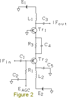
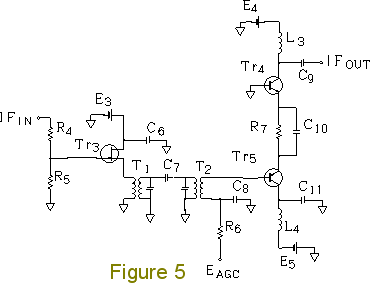
Forward AGC-based Single Superheterodyne RX25. Single Superheterodyne Receiver RX25 using forward AGC (automatic gain control) Intermediate-frequency (IF) amplifier of RX25. Figure 2 shows an IF amplifier circuit of the forward AGC-based single superheterodyne receiver RX25. Transistor Tr1 (2SC2348) is used in the grounded-base circuit (common-base circuit). The common-base circuit is more advantageous to the 2SC2348 than the common-emitter circuit, because oscillation is encumbered by the common- base circuit. The 2SC2348 is an NPN transistor for forward AGC. C2, C4, and C5 are bypass capacitors. In Figure 2, a PNP transistor Tr2 (2SA836-D) is used in the common-collector circuit (emitter follower). In the previous receiver RX24 and other receivers, I have used 2SA970 PNP transistors several times. C1 and C3 are coupling capacitors. With L1 and C3, the IF amplifier outputs a signal. L1 is an inductor (coil) of 3.9 mH, which is easy to obtain. Such a coil can be used even at 455 kHz. A current of 20 mA may flow through coil L1. L2 is an inductor of 220 microhenrys. The collector current may exceed approximately 6 mA. In such cases, the higher the collector current, the lower the gain of 2SC2348. (The hFE-Ic characteristics are shown on page 337 of Transistor Gijutsu September 1996, CQ Publishing Co., Ltd.) As the maximum rating of 2SC2348, a collector current of up to 20 mA is acceptable. In order to establish forward AGC, the bias is adjusted so that when no signal is input, the collector current may be approximately 6 mA. In addition, the bias is designed so that even the strongest signal cannot cause the collector current to exceed 20 mA. R3 is a resistor of 150 ohms which has the ability to limit the current. The IF amplifier operates on a positive power supply E1 of +6.4 V and a negative power supply E2 of -4.3 V. Even if AGC voltage EAGC reaches -4.3 V, the collector current will not exceed 20 mA because of the current-limiting function of R3. Be careful that EAGC does not reach -4.3 V. R1 is a resistor of 1-2 kilohms. The positive power supply E1 of +6.4 V and the negative power supply E2 of -4. 3 V are stabilized. Inter-stage double-tuned circuit (RX25). The RX25 has two IF amplifier stages. Figure 5 shows a double-tuned circuit interposed between the first and second stages for excellent frequency selectivity. Note that the RX25 has a ceramic filter CFW455HT (not shown) interposed between a mixer circuit (frequency converter) using the MC1496 and the IF amplifier circuit. T1 and T2 are intermediate-frequency transformers (IFTs) for transistors. In the RX25, IFTs with white coated cores (Toko IFZ-455B) are used. In the RX24 and other receivers, I have used IFTs with yellow coated cores several times. The double-tuned circuit is composed of two IFTs and a capacitor C7 of 4 pF which couples them. Tr3 is a junction-type field effect transistor (JFET). The 2SK54-C is used. IFIN in Figure 5 is connected to IFout in Figure 2. Resistors R4 and R5 compose a voltage divider, with which gain can be adjusted. Thus, it is possible to allocate gain deliberately to RF, IF, and AF amplifier stages of RX25. At present, the ratio of R4 to R5 is 36 kilohms : 3.6 kilohms. IFT T1 has a low-impedance winding connected directly to the source of Tr3. FET Tr3 functions as an impedance converter (source follower).
Powered by w3.css
 Home
Home