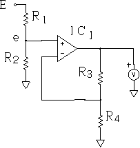
The electronic voltmeter is very useful for oscillation check. Principle of electronic voltmeter. Figure 1A shows the principle of home-made electronic voltmeter P6. IC1 is the LF411 operational amplifier. IC1 and resistors R4 and R5 compose a noninverting amplifier. It operates on power supplies of -9 V and +9 V. Bypass capacitors are added to the operational amplifier (op-amp). Offset adjustment is made with a variable resistor RV16YN B103 (10 kilohms, not shown). Lugs 1 and 3 of the variable resistor are connected to pins 1 and 5 of the operational amplifier. Lug 2 is connected to the power supply of -9 V. As R4 and R3, BI Technologies (Beckman) resistor network 898-3-R10K (8 resistors of 10 kilohms) is used to output one-eighth of the input voltage. The input of such a voltage divider is connected to the op-amp output. The noninverting amplifier, therefore, has a voltage gain of 8. The LF411 has a sufficient swing output voltage to enable a voltmeter (Okusawa KSM-45) to indicate 5 V. When the noninverting input is 0.625 V, the voltmeter indicates 5 V. Resistor R1 provides a high input resistance of 10 megohms.
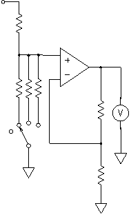
Resistor R2 is determined by calculation and by experiments. The electronic voltmeter P6 can be used as the 5-V meter, the 25-V meter, or the 2.5-V meter by selecting with Alps rotary switch Y-104 (1 wafer, 3 poles, 4 positions). Grounding the rotor contact (that is, common for the pole) produces one open state (Figure 1B). When the open state is selected, it is theoretically possible to use the electronic voltmeter P6 as the 0.625-V meter. Note that while selecting, you have to make the rotary switch momentarily open. Do not turn the rotary switch while measuring, or the noninverting input will exceed the full-scale range of 0.625 V.